.png)
From the noisy corners of an industrial plant to the quiet and minimalist interior of a laboratory, there is a language that is not heard, but speaks volumes: Modbus. It is the language of PLCs, sensors, and controllers, which communicate with each other to continue generating products, raw materials, medicines, etc.
Modbus is an open industrial communication protocol developed in 1979 by Modicon (now Schneider Electric), designed to enable the transmission of information between electronic devices. Its main purpose is to facilitate communication between programmable logic controllers (PLCs), sensors, actuators, SCADA systems, and other industrial equipment. Its operating principle is one asks, one answers (Master-Slave).
Key Features:
-
Available Protocols:
-
Modbus RTU (over RS-485): efficient and widely used in the field.
-
Modbus ASCII: less common, more readable, but slower.
-
Modbus TCP/IP: modern version for Ethernet networks.
-
-
Common data types:
-
Coils: Digital outputs.
-
Discrete inputs: Digital inputs.
-
Input registers: Read-only analog values.
-
Holding registers: Variables that can be read or written.
-
-
Standard functions:
-
Reading and writing bits and words (16-bit registers).
-
Diagnostics and basic remote control.
-
But let's start from the beginning, and there's nothing more basic than knowing how it works and how it's classified:
-
Modbus and the OSI pyramid
The OSI (Open Systems Interconnection) pyramid is a reference model that divides network communication into seven layers, from the physical to the application:
-
Physical layer
-
Data link layer
-
Network layer
-
Transport layer
-
Session layer
-
Presentation layer
-
Application layer
Where is Modbus in the OSI pyramid?
Modbus is a layer 7 protocol, the application layer. This means that Modbus defines the format and meaning of the messages sent and received to control and read industrial devices. However, Modbus does not define either the physical layer or the data link layer, which are responsible for the actual transmission of bits and managing communication in the physical medium.
What does it mean that Modbus is not the physical layer?
-
The physical layer refers to the physical transmission medium, for example: RS-232, RS-485, Ethernet, fiber optic cables, etc.
-
Modbus can operate over different physical media. For example:
-
Modbus RTU uses RS-485 or RS-232 as the physical layer and defines how to structure serial messages.
-
Modbus TCP uses Ethernet (physical and data link layers) and TCP/IP (network and transport layers) to transmit its messages.
-
Therefore, Modbus is not a standard for cables or electrical signals, but rather a protocol that sits on top of other layers so that devices can understand each other.
This means that what truly defines the protocol is how it interprets the bits it reads from the different physical layers, which in their basic structure are as follows:

In Modbus, data types can be divided into two main types: coils and registers.
Coils can be defined as digital, as they can only be ON (1) or OFF (0). Some coils can represent inputs, while others can represent outputs.
Registers are 16 bits (2 bytes) unsigned and can therefore have values from 0 to 65535 (0 to FFFF). However, they have limitations, such as not being able to represent negative numbers, floating-point numbers, or values with representations greater than 65535. However, some manufacturers use two or more registers to create floating-point or negative numbers.
Knowing that it's a Master-Slave-based protocol, how many devices can be connected to the network?
The answer is... it depends.
The standard limit is up to 32 devices total (1 master + 31 slaves), without repeaters, but let's analyze each possible scenario:
Modbus ASCII (RS-232 or RS-485)
With RS-232 (point-to-point):
-
Only 2 devices (1 master and 1 slave).
-
RS-232 is not multidrop, so it doesn't allow more than two devices.
With RS-485 (as RTU):
-
Same logic as RTU: up to 32 without repeaters, up to 247 with them.
Modbus RTU (RS-485)
-
Up to 32 devices total (1 master + 31 slaves), without repeaters.
With RS-485 repeaters:
-
You can reach up to 247 slaves, which is the logical limit of the Modbus protocol (addresses 1 to 247), if you use repeaters to regenerate the signal and increase the electrical fan-out.
Modbus TCP/IP (Ethernet)
Theoretically:
-
The protocol uses IP addresses, so the practical limit is enormous.
-
Unit ID: typically 1 to 247 (for compatibility with serial slaves through gateways).
-
Number of nodes on the Ethernet network: depends on IP addressing, switches, routers, and traffic.
In practice:
-
You can have hundreds or thousands of devices, as long as the Ethernet network supports it.
-
What's important: there is only one master per Modbus TCP connection, but there can be many simultaneous clients if the server/slave supports it.
Modbus is a communications protocol, not a network topology per se. However, the way a Modbus network is physically connected, especially Modbus RTU over RS-485, typically adopts a daisy chain topology. A daisy chain network is a form of connection in which each device is connected in series to the next, forming a single communication line:

That is:
Master ─── > Slave 1 ─── > Slave 2 ─── > Slave 3 ───> Terminator
Why does Modbus RTU use daisy chain?
RS-485 is a half-duplex multidrop bus, allowing up to 32 devices to be connected on a shared line (with repeaters, up to 256 or more).
RS-485 has a single differential line (A/B), and all devices must be connected in parallel, respecting the bus impedance.
To avoid reflections, terminating resistors are placed at the ends of the chain.
Although the physical connection looks like a direct line, in practical terms it is implemented as a chain—hence the name daisy chain—where the cable "hops" from slave to slave.
And what about Modbus TCP?
Modbus TCP/IP does not use daisy chain because it is based on Ethernet, which typically uses star (with switches) or mesh (in redundant industrial networks) topologies.
In short, Modbus is an open and reliable standard, whose longevity demonstrates its effectiveness. It is the right choice when a simple, interoperable, and well-documented solution is needed for industrial communications. It also has a faster response time than, for example, HART, another industrial digital communication protocol. This makes it suitable for simple control systems that do not respond as quickly as temperature.
Example:
Sometimes it's very complex to read an article and learn simply from the theory, so at Axotek we've prepared an example that can be very useful in certain cases, such as the following:
Imagine you arrive at the plant and find a Coriolis mass flow meter, which you need to know the total flow rate. But, surprise, the device is blind, meaning it doesn't have a display, but it does have a Modbus RTU 485 communication port. There are several ways to solve the problem:
1. Purchase the software from the manufacturer; this can be expensive in certain cases.
2. Search the internet for Modbus reading software such as Modbus Slave or Modbus Poll, but these are usually very complex if you're a beginner.
3. Download the Excel file we have at Axotek and modify it to your needs.
For this last case, which is what we'll focus on, we'll need two files: an Excel file and an ActiveX library (OCX). ActiveX libraries are typically paid and licensed, but we'll use the one developed by Modbus Tools. The free version allows you to run for 60 minutes, and then you just need to restart the connection to have another 60 minutes. You can also purchase the paid version for unlimited access.
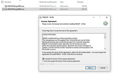
Step 1: Download the two files:
You can also download Mbaxp from the official Modbus Tool website: https://www.modbustools.com/download.html
There are several considerations regarding the files:
- This only works with Windows operating systems.
- When downloading, you must unzip the *.zip file.
- In the case of Excel, it is an *.xlsm file, so it is an Excel file with macros; you must have them enabled. Also, when downloading the file, you must unzip it and right-click. In the General tab, select Unlock at the bottom. *Don't worry, you can scan it with your antivirus before or after unzipping.*

2: Once you have the two files (Excel and Mbaxp) the first thing required is to install the ActiveX library, then you just have to double click on the MBAXPSetup.exe file (choose 32 Bit or 64 Bit) and follow the instructions, once finished the window will close and you will be ready to open Excel.
3: Once installed, we proceed to open Excel, make sure you have the developer tab active, if it is not active in Excel Options > Customize Ribbon > and select Developer:

We will base this practical example on how to visualize a Micro Motion CMF series Coriolis flowmeter, which has a Modbus output port. For this project, we need to display the following variables:
- Instantaneous flow
- Density
- Temperature
- Mass totalization
And, additionally, the ability to reset the totalization to create batches.
4: We will download the Modbus mapping manual from the manufacturer's website and identify the variables we want to read and write, as well as the type of message to be sent. Remember that when installing Mbaxp, Excel becomes the Master and the device becomes the Slave.
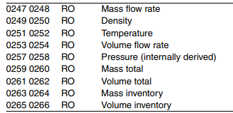
In the case of reading the variables, the manual states that they are Floating-point register pairs, so we will have two registers, each of which is RO = Read-only:
-Flow: 247/248 RO
-Density: 249/250 RO
-Temperature: 251/252 RO
-Total Mass: 259/260 RO
So we must enter this information in this section of Excel in the "Inicio" workbook:

You may be wondering why, if the flow addresses are 247/248, according to the manual, the addresses 246 are entered in Excel with a length of 2 (second green column). Well, this is because there are two ways to document Modbus registers: the logical address and the Modbus address, but what is each one?
The logical address is a base-1 address, and it is widely used in manuals because it is more understandable to start at address 1.
The Modbus address is the one with a base of 0; the registers are indexed from zero.
That is:
Holding Register 1 → address 0 (in the protocol).
Also, in many documents, Holding Registers can be presented as 40001, 40002, 40247, etc. However, in actual Modbus transmission, the initial 4 (which indicates "holding register") is omitted and the output starts from 0.
If you enter 2 in the second column (green), it means you are going to read two consecutive registers 246/247.

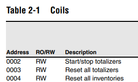
The manual mentions that a coil must be activated to reset the totalizer, so we must write a coil. The manual specifies that it is number 3. Therefore, following the previous reasoning, we will enter number 2 in the "Write Coil" section.
5: Once we have researched and entered the data we will read and write, it is important to physically connect the device to the computer. This typically requires the use of a USB to RS485 converter:

It can be any brand, and some are quite inexpensive. You just need to correctly install the manufacturer's drivers on your PC and know which COM port it's associated with. You'll also need to make the physical connection to the device according to its user manual:

Remember that RS485 adapters can be 2 or 3 wires (A, B, and ground). In this case, we will use only one of the 2 wires, A and B. The A of the RS485 adapter must be connected to the A of the measuring device, and the B to the B.
The following must also be configured:
Baud Rate:
Stop Bit:
Parity:
Data Bit:
Slave ID:
These data are usually included in the user manual, unless they have been modified. In this case, you should request these values from the person in charge of the equipment.
For the COM port, you can view it in the PC's Device Manager:

For the test we will do with a Micro Motion flowmeter, it is configured in Excel as follows:
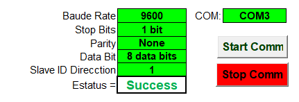
Once everything is configured, all that's left is to press the "Start Comm" button and that's it. A window will open informing you that you have 60 minutes left to use Modbus. When you press "Accept," a window will open showing the communication status.

If the message does not appear, it means that you have blocked the ActiveX settings, you just need to enable them in the Excel Trust Center:

If everything was done correctly, a window will open in which you can see the variables sent by the slave device and that you entered through the Modbus registers. You can also reset the total by pressing the "Reset Total" button.
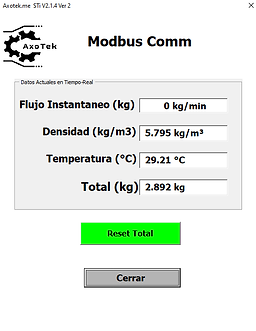
And with this, you'll be able to view the variables you need in real time.
If you want to customize Excel for your project, it's also very simple. Just go to the "Developer" tab and then "See code."

By opening the Forms section and then in UserForm1, you can modify the interface to your liking to make it fit your project:

Remember that you can adapt this for any sensor, meter, or device that communicates via Modbus. It doesn't replace the manufacturer's software. This is for applications that need to be adapted to your needs. If you need to read or write other types of Modbus registers, the Mbaxp installation folder contains the code guide to do so:
